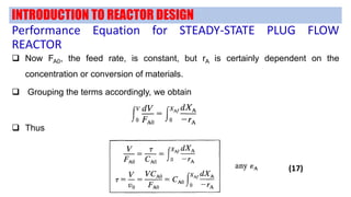
plug flow reactor equation
7-5n and 7-5c required numerical integrations. The general equation is summarized in 8.

Isothermal Plug Flow Reactor Part 1 Youtube
8 C out C C in C exp K q with.
. Derive basic reactor performance equations using ideal flow patterns for the various phases. Introduce non-ideal fluid mixing models. Plug Flow Reactor PFR The third general type of reactor is the Plug Flow Reactor PFR.
It can be derived directly from the rate equations with the aid of Laplace transforms. δ s 5 ν u displaystyle delta _sfrac 5nu u u τ w ρ 1 2 displaystyle uleftfrac tau _wrho right12. Illustrate concepts through use of case studies.
Two template examples based on a capillary geometry are the plug flow ideal reactor and the non-ideal Poiseuille flow reactor 3. 15 represents the characteristic equation for a CSTR. For steady-state operation in which no work is done by the system Equation R137-3 reduces to R137-6 Substitution for the molar flow rates F i in terms of conversion gives Equation R137-7.
Assuming a first-order reaction 1 1 out in H c ck. Q is the hydraulic loading rate m yr. The main assumptions of this model are that the fluid is completely mixed in any cross-.
In a plug flow reactor nutrients and sometimes organisms are introduced to the reactor continuously and move through the reactor as a plug. The volumetric flow rate F divided by the reactor cross-sectional area A is equal to the superficial velocity through the column u. Plug flow reactor.
Use this equation for steady-state energy balance on a. R A - dF Ai dV. K is the first-order aerial rate constant m yr 1.
The step wise derivation of performance equation for Plug Flow Reactor and their typical characteristics are discussedPlug Flow ReactorFlow ReactorPerfor. However perfectly-mixed flow reactors behave differently. The fixed-bed laboratory reactor is regarded as an ideal isothermal plug flow reactor.
The system may be either contained as in a water main oil pipeline or blood vessel or open as in a shower curtain stream or. For F and A constant u is also constant. The total mass of the reactors contents changes as a result of flow through the reactors inlets and outlets and production of homogeneous phase species on the reactor walls.
Plug flow will be achieved if the sublayer thickness is much less than the pipe diameter. The rate equation is. 1481 u s z Δ z s z Δ z v max s K m s.
Made by faculty at the Universit. Derivation of the design equation for a plug flow reactor with second order kinetics. Where C is the background pollutant concentration mg l 1.
No volumetric flow variation. Equation 1481 applies to. 16 A Plug Flow Reactor PFR consists in a long straight pipe in which the reactive fluid transits at steady-state no accumulation.
The sequences of second-order reactions of Figs. In an ideal PFR concentration is a function of both distance along the flow path x and time t. There is no doubt that the conversion of this fraction of fluid is.
531 one can see that the fraction of fluid particles with residence time shorter than t over the total fluid is F t 1 e1 0632. Presented by Professor Alan Hall University of Huddersfield. F Ai QA i.
Q 365 Q A S. In case the volumetric flow within the reactor stays constant Q i Q o Q at any point in the reactor the reaction speeds above can be simplified and expressed as a function of the concentration. Beginequation fracdmdt sum_in dotm_in - sum_out dotm_out dotm_wall endequation.
Review ideal flow patterns for homogeneous systems as a precursor for application to multiphase systems. This is the equation for a plug flow reactor. The reactor model consists of the continuity equations for 1 N 2 CO NO O 2 CO 2 N 2 O and NO 2 in the gas phase 2 surface species adsorbed on the noble metal surface 3a surface species adsorbed on the ceria surface 3b species in the ceria sub-layer 4 CO 2 adsorbed on the γ.
Because in the plug flow reactor there is a single velocity v0 with a velocity probability distribution Pv v0 16 v - Vo the residence time distribution for capillary of length L is the normalized delta function RTDt T 1St-1 where x Iv0. A reversible reaction A B is conducted in a plug flow reactor. C Cxt For a mass balance on a reacting compound take mass balance on differential axial element with uniform reaction potential concentration where dV differential volume A cross sectional area dx differential distance and dV Adx.

Plug Flow Reactor Model A Plug Flow Reactor Pfr Model Is Used By Justin Mitchell Medium

Plug Flow Reactor Pfr Sizing And Conversion Example Youtube

L 2 1 Review What Size Reactors To

Introduction To Energy Balances For Plug Flow Reactors Youtube
Matlab In Chemical Engineering At Cmu
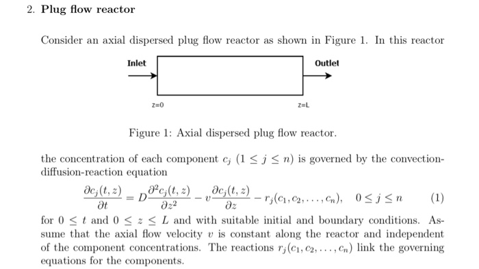
2 Plug Flow Reactor Ler An Axial Dispersed Plug Flow Chegg Com

Plug Flow Reactor Design Equation Youtube

Computational Scheme For A Plug Flow Reactor Defining The Function Download Scientific Diagram

Mole Balance On A Plug Flow Reactor Youtube

Design Equation Of Plug Flow Reactor Chemical Reaction Engineering Lecture 08 Hindi And Urdu Youtube

Plug Flow Reactor Overview Youtube
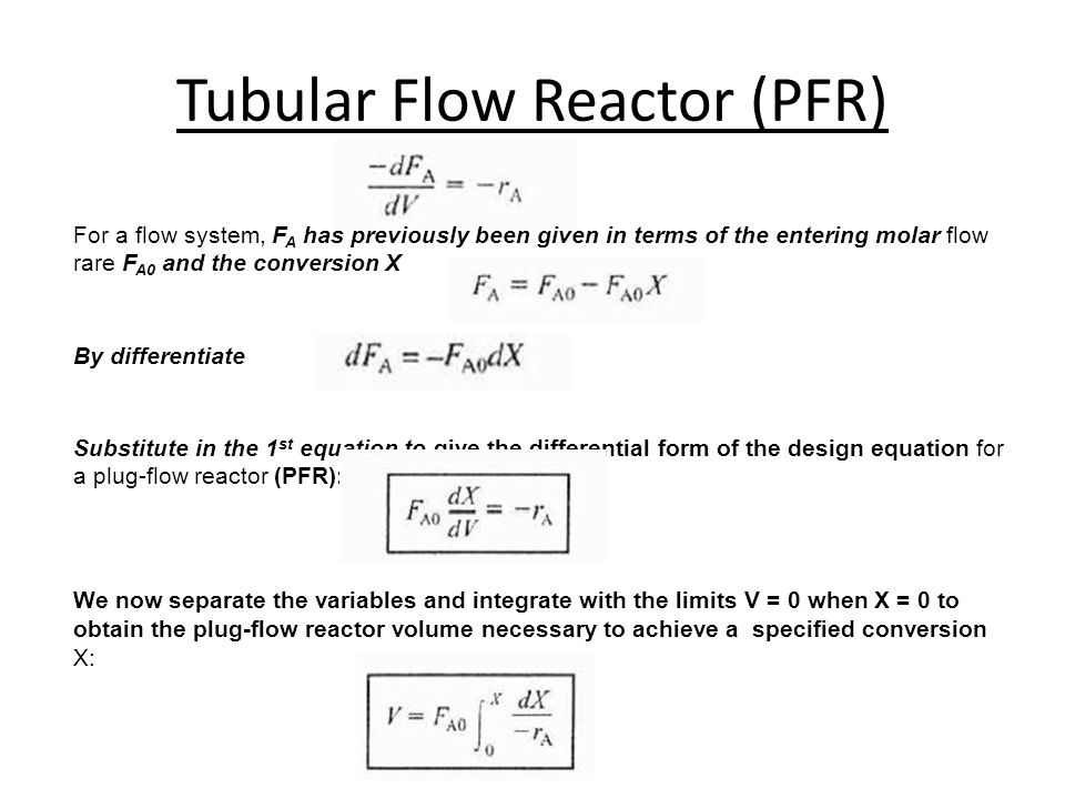
Conversion And Reactor Sizing Lec 4 Week 4 Definition Of Conversion For The Following Reaction The Reaction Can Be Arranged As Follows How Far The Above Ppt Download
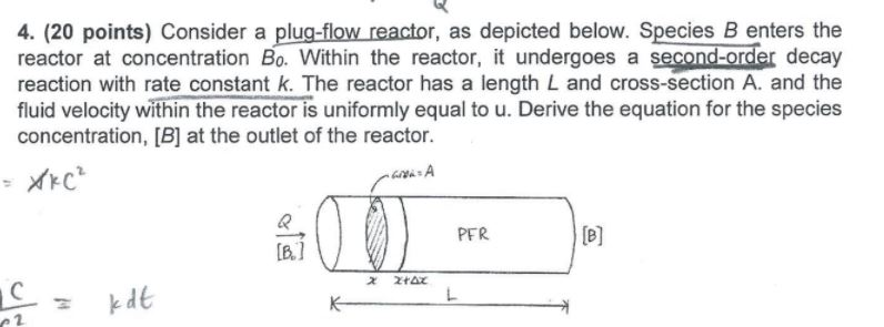
Solved 4 20 Points Consider A Plug Flow Reactor As Chegg Com

Plug Flow Reactor With Second Order Kinetics Design Equation Youtube

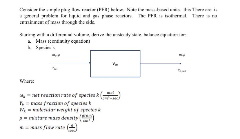
Solved Consider The Simple Plug Flow Reactor Pfr Below Chegg Com

Plug Flow Reactor With First Order Kinetics Performance Equation Youtube
